Table of Content
ATmega328 comes with preprogrammed onboard boot loader which makes it easier to upload the code without the help on external hardware. It has vast application in making electronics projects or products. The C and C++ language is used to program the board which is very easy to learn and use.

There are lots of ways to use automated lighting, beginning with programming lights to go on and off at certain times of the day. For a lot of people, the introduction into home automation starts with a smart thermostat. A smart thermostat is not merely a programmable thermostat, it is one that can ‘learn’ your habits and adjust itself automatically.
What is Component Diagram
Switch off the load by mobile ,if already on from starting. Relay should be used with a driver circuit of Transistor and diode to make it work properly, check here for more detail. And ULN2003 IC has inbuilt darlington transistor pairs and other circuitry to drive relay. You can use the same circuit but you have to replace the Relay for handling 440 v, the relay used in this circuit can handle upto 250v. Smart appliances with the management are here and also provide status information to the users remotely. Smart lighting for home helps in saving energy by adapting the life to the ambient condition and switching on/off or dimming the light when needed.
In this project, we are going to use Arduino UNO to control home appliances automatically. It has ATmega328 microcontroller IC on it which runs on 16MHz clock speed. It is a powerful which can work on USART, I2C and SPI communication protocols. This board is usually programmed using software Arduino IDE using a micro USB cable.
Programming Code Explanation
Off The MRKT, is a real estate lifestyle website based in New York City. Port is used when the component delegates the interfaces to an internal class. 3) Rectangle with the component icon and the component stereotype. 2) Rectangle with the component icon in the top right corner and the name of the component. They are used to control a high voltage circuit with a small voltage signal.

In this article, we will discuss the overview of IoT home automation. And will focus on smart lighting, smart appliances, intrusion detection, smoke/gas detector, etc. Anyone can control the appliances by calling the mobile connected to module.
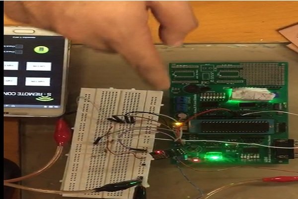
Remote controlled Home automation without using microcontroller (Part- Schematic Circuit Diagram
With a perfectly blended team of Engineers and Journalists, we demystify electronics and its related technologies by providing high value content to our readers. Easiest way is to use exclusive sim card for that mobile, otherwise you need use some microcontroller and GSM module to filter the incoming mobile number. Here in dis components list they have mentioned about PVT, I just wanted to know what is PVT and what are its uses and application. Now if we need to ON LIGHT and FAN so we need to press key3 . And now we want to ON TV so we need to press key 7 not key4. Because we should keep remain turn ON previous appliances.
In these modern days, everyone wants their smart home where all electronic or electrical devices and home appliances can be controlled remotely. In this project, we will make a new type of Bluetooth control Home Automation system, where we can control home appliances wirelessly through Bluetooth communication technology. In this smart home automation system, we will control home appliances using the Voice command and button command.
At the same time, the “D1 is ON” status print on the 16×2 LCD Display Module. First, we start by including the software serial library, which will be used to establish communication between the HC-05 Bluetooth module and the app. Here we have connected a cell phone using aux wire to the DTMF decoder circuit. Before explaining the further working of project we need to know about the output of DTMF decoder for every key pressed.
School Automation System UML component diagram, describes the organization and wiring of the physical components in a system. Interfaces in component diagrams show how components are wired together and interact with each other. The assembly connector allows linking the component’s required interface (represented with a semi-circle and a solid line) with the provided interface of another component. This shows that one component is providing the service that the other is requiring. Again the Arduino gets this value through the Bluetooth module.
Relays come in different sizes and varieties according to their use in circuits. The main applications of the relay include motor control, automotive applications, industrial applications, home automation, etc. At first, Click on the Settings button 1,if your smartphone pair with the HC-05 Bluetooth module, then you can see the “HC-05 Bluetooth” name on this page. If your app is successfully connected to the Bluetooth module, then you can see the LED on the Bluetooth is start blinking with a delay.
But this time the Arduino sends a High input voltage to the Input-1 pin of the relay module. So the Light will also turn off, which is connected to the relay-1 of the relay module. At the same time, the “D1 is Off” status print on the 16×2 LCD Display Module. Then the Arduino gets this value through the Bluetooth module. Then the Arduino sends Lowvoltage to the Input-1 pin of the relay module. So, the Light will also turn on, which is connected to the relay-1 of the relay module.
HC-05 Bluetooth module has built-in red led which indicates the connection status. Before any connection it blinks continuously in some periodic manner and after it gets connected its blinking speed slows down. Home automation is a booming industry with a lot of potential. Whether you buy a system or build your own, the four components listed here make for a good starting point. You can add-on with additional components after you get a better idea of how home automation can work for you.
The output pins of DTMF IC (i.e. 11 – 14) are connected to PB0-PB3 pins of controller. Output pins of the controller i.e PD0 and PD1 are connected to relay. Relay output is connected to AC source i.e. light or fan.
In the void setup, we set up the serial monitor and virtual Bluetooth serial at 9600 baudrate. Next, make a function to auto-connect to the HC-05 Bluetooth module when the screen is initialized. If the connection is successful, we show an alert, saying that the connection was successful.


No comments:
Post a Comment